
The short answer
How do driven and parasitic elements work in the Yagi–Uda antenna?
Compare the evidence
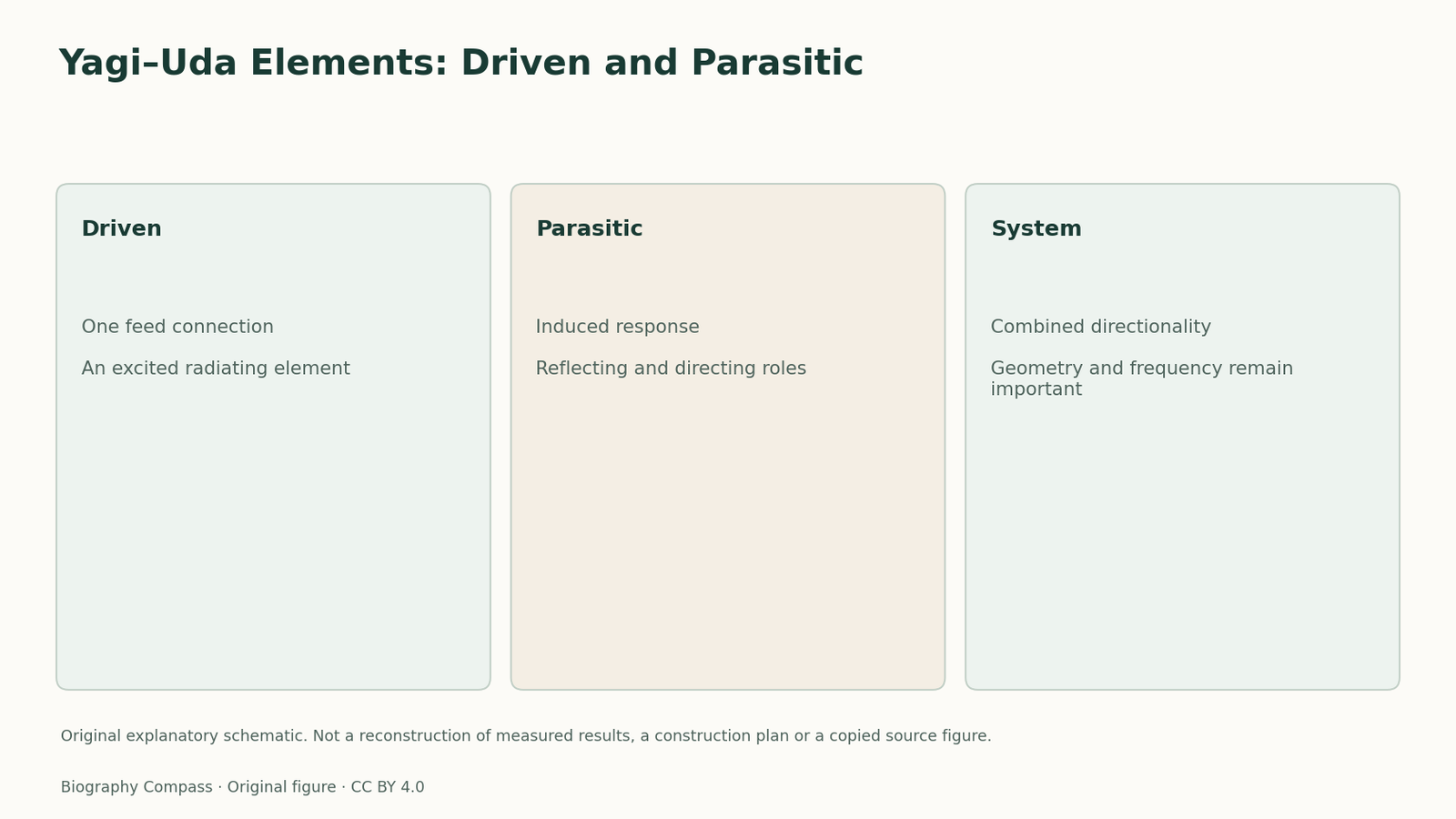
Yagi–Uda Elements: Driven and Parasitic
Compare what each inspected record establishes with the claim that remains separate.
| Record or observation | What it supports | What remains separate |
|---|---|---|
| 1926 primary description | Distinguishes the driven antenna and currents induced in nearby rods | Does not make every unconnected rod inert |
| IEEE milestone account | Identifies closely coupled parasitic elements as central | Does not supply a measured pattern for the classroom schematic |
Not every rod has a direct electrical feed
The joint 1926 paper begins with a radiating antenna and a nearby metallic rod in its field. It describes a current induced in that rod and relates its behaviour to the rod's electrical length. This is the basis for distinguishing the driven element from parasitic elements participating through coupling. A rod without its own feed is therefore not necessarily inactive. Its response can affect the combined directional behaviour of the arrangement.
Reflectors and directors have different roles
Yagi and Uda discuss rods acting as reflectors and others acting as directors, and combine them in arrangements intended to concentrate radiation. Their paper gives particular geometry and measurements. The IEEE milestone describes the achievement in terms of closely coupled parasitic elements. This guide keeps the functional distinction while omitting unchecked numerical design rules. It does not claim that any row of metal rods will provide the same performance, or that the same dimensions work at every frequency.
A feed-and-response exercise
Draw an original classroom antenna diagram with one labelled feed connection and several nearby rods without feed wires. Ask which element receives a direct input and which elements respond through coupling. The answer distinguishes driven from parasitic; it does not calculate gain or a beam shape. Add a second question: would removing a feed wire from a drawing prove that a rod has no electrical effect? It would not. The schematic teaches a functional classification, not a construction recipe, a measured radiation pattern or a reproduction of the 1926 apparatus.
Continue the chronology
Related history guides
Biography context
Explore Japan through connected lives
Connected biographies
People behind the records
1896–1976
Shintaro Uda
Communications engineer and directional-antenna researcherExperimental development of the Yagi–Uda directional antenna.Read biography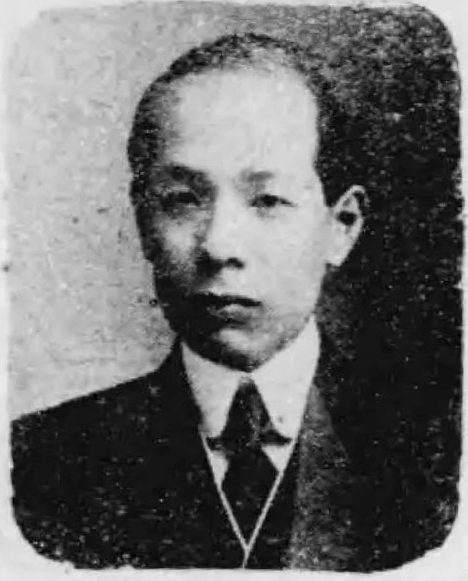
1886–1976
Hidetsugu Yagi
Telecommunications engineer and university leaderJoint directional-antenna work with Shintaro Uda and international communication of that research.Read biography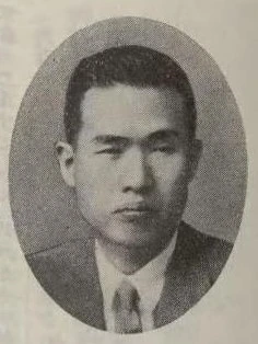
1899–1990
Kenjiro Takayanagi
Television engineer, researcher and educatorA1926 television demonstration using mechanical scanning and a cathode-ray-tube display.Read biographyQuick answers
Common questions
- How do driven and parasitic elements work in the Yagi–Uda antenna?
- The driven element has a direct feed. Parasitic elements respond through coupling; their induced currents affect the system’s directional behaviour, so lacking a feed does not mean lacking an electrical effect.
Primary and institutional sources
How this history was checked
Sources distinguish individual patent or technical records from biographical and retrospective accounts. Their actual reading scope is retained in the biography source notes. This article was reviewed on 7 November 2026.
- Tohoku University Digital ArchiveProfessor Shintaro Uda, archive recordC004326
- H.Yagi and S.Uda / Proceedings of the Imperial Academy,1926Projector of the Sharpest Beam of Electric Waves
- Qiang Chen / Proceedings of the Japan Academy,2025First English article of Yagi-Uda antenna
- IEEE Japan Council milestone recordDirective Short Wave Antenna,1924