
The short answer
What could Baker’s human cantilever demonstration explain, and what required structural calculations?
Read the records together
Contributions,evidence and scope
Different records illuminate different parts of this particular undertaking.
| Record | What the record establishes | What remains distinct |
|---|---|---|
| Human-model teaching account | Explains load transfer and balance visibly. | Does not certify a full-scale railway structure. |
| Baker’s historical biography | Connects long-span study with cantilever design. | A principle alone does not specify all dimensions. |
| Construction archive | Preserves stages, drawings and institutional records. | A photograph is not a complete calculation set. |
The demonstration explained a load path
Baker’s human cantilever model represented an outward-reaching structure supported from stable bases. Princeton’s teaching account describes people, chairs, struts and anchoring weights forming a system that could carry a central person. The visible arrangement made an unfamiliar bridge principle easier to follow: load passed through connected members to supports rather than disappearing into a visually balanced pose. The model’s value was explanatory. It allowed an audience to discuss the relation between reaching arms, support and balance before confronting the scale of the Forth crossing.
Sources for this section: [3]
A real bridge required more than resemblance
The historical biography connects Baker’s early long-span studies with cantilevers carrying an independent central girder. At the Forth, that principle had to become a steel structure on foundations across an exposed estuary. A person in a model is not a scaled railway train, and a chair is not a tested granite pier. Thus the demonstration and full-scale engineering answered different questions. One made the structural idea legible; the other required dimensions, material properties, construction arrangements and loads. This distinction explains the model’s usefulness without treating it as a safety certificate or dismissing it as a publicity trick.
Photographs record different kinds of evidence
National Records of Scotland preserves the demonstration photograph alongside hundreds of construction images made by assistant engineer Evelyn Carey. A model photograph documents an explanatory event. Progress photographs document particular stages in building, such as the erection of members and the approach to joining spans. Neither should be asked to provide an entire set of calculations from appearance alone. Used together, however, they connect communication with construction. The archive also identifies parliamentary material and drawings as further record types. The narrative therefore has several evidential layers rather than one iconic image standing for the whole project.
Sources for this section: [2]
Compare a model with a construction record
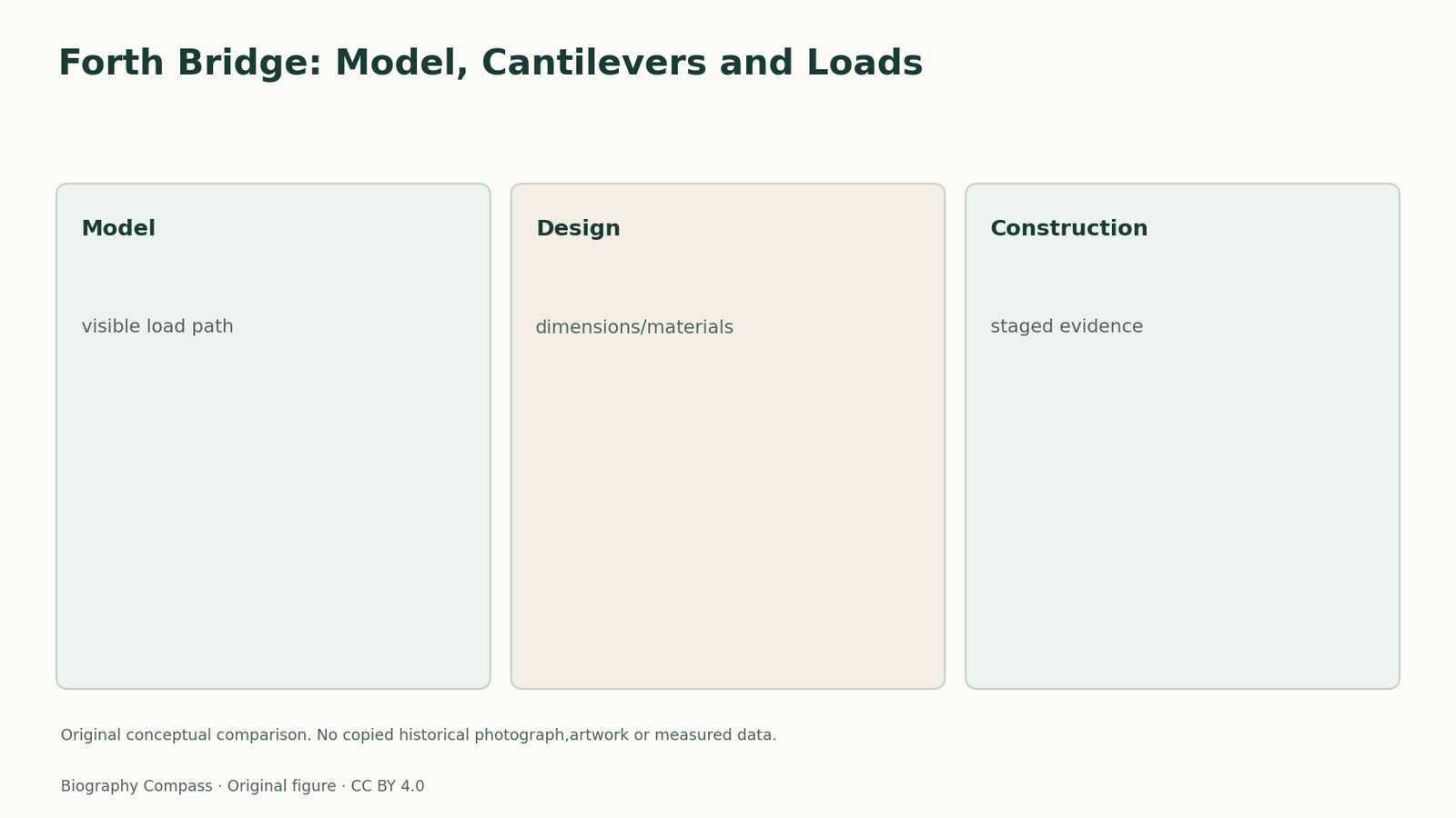
Make two columns: what the model makes visible and what a full design must specify. In the first, place an outward load path, connections and balance. In the second, place material strength, member dimensions, foundations and the loads to be carried. Then ask whether a successful demonstration proves that an arbitrarily enlarged bridge would work. The checked answer is no: scaling changes the physical problem and requires its own design evidence. This original exercise does not reproduce the human demonstration physically or prescribe a classroom lifting activity. It is a paper comparison that preserves the model’s positive purpose while explaining why Baker’s structural studies and the construction team remained indispensable.
Continue the chronology
Related history guides
Forth Bridge: Partnership, Approval and Building
Map Fowler, Baker and the contractors’ roles on the Forth Bridge using design reports, contract dates and construction records, with a worked exercise.
Read the timeline1851–1855Niagara 1855: A Railway Suspension Bridge
Examine how Roebling’s Niagara railway suspension bridge combined cables, deck stiffness and construction decisions to carry changing railway loads.
Read the timelineBiography context
Explore United Kingdom through connected lives
Connected biographies
People behind this work
1840–1907
Benjamin Baker
Civil and structural engineerBenjamin Baker is remembered for developing long-span bridge engineering with John Fowler and contributing to underground railways and the Aswan Dam.Read biography
1806–1859
Isambard Kingdom Brunel
Consulting civil engineer for railway, bridge, dock and steamship enterprisesIsambard Kingdom Brunel ran an engineering practice serving railway and maritime companies. As the Great Western Railway’s engineer, he helped connect London and Bristol in 1841. His ships and structures combined technical ambition with financial risk and depended on investors, contractors and workers.Read biography
1789–1874
William Fairbairn
Millwright, manufacturer and experimental engineerWilliam Fairbairn moved from millwright work into iron manufacturing, combining structural experiments with the practical organisation of workshops and boiler safety.Read biographyQuick answers
Common questions
- Did Baker’s human model prove the full bridge’s safety?
- No. It explained load paths and balance; the real bridge required full-scale design, materials, foundations and construction evidence.
Primary and institutional sources
How this history was checked
The cited records distinguish contemporary accounts,official catalogues and later institutional or scholarly interpretation. The comparison and worked exercise are original editorial material. This article was reviewed on 7 November 2026.
- Dictionary of National Biography, original 1912Baker, Benjamin
- National Records of ScotlandForth Bridge: Portraits of a Scottish Icon
- Princeton University, Creative Art of Structural and Civil EngineeringThe Human Cantilever Model of the Forth Bridge
- Forth Bridges official historyThe Forth Bridge Builders