
The short answer
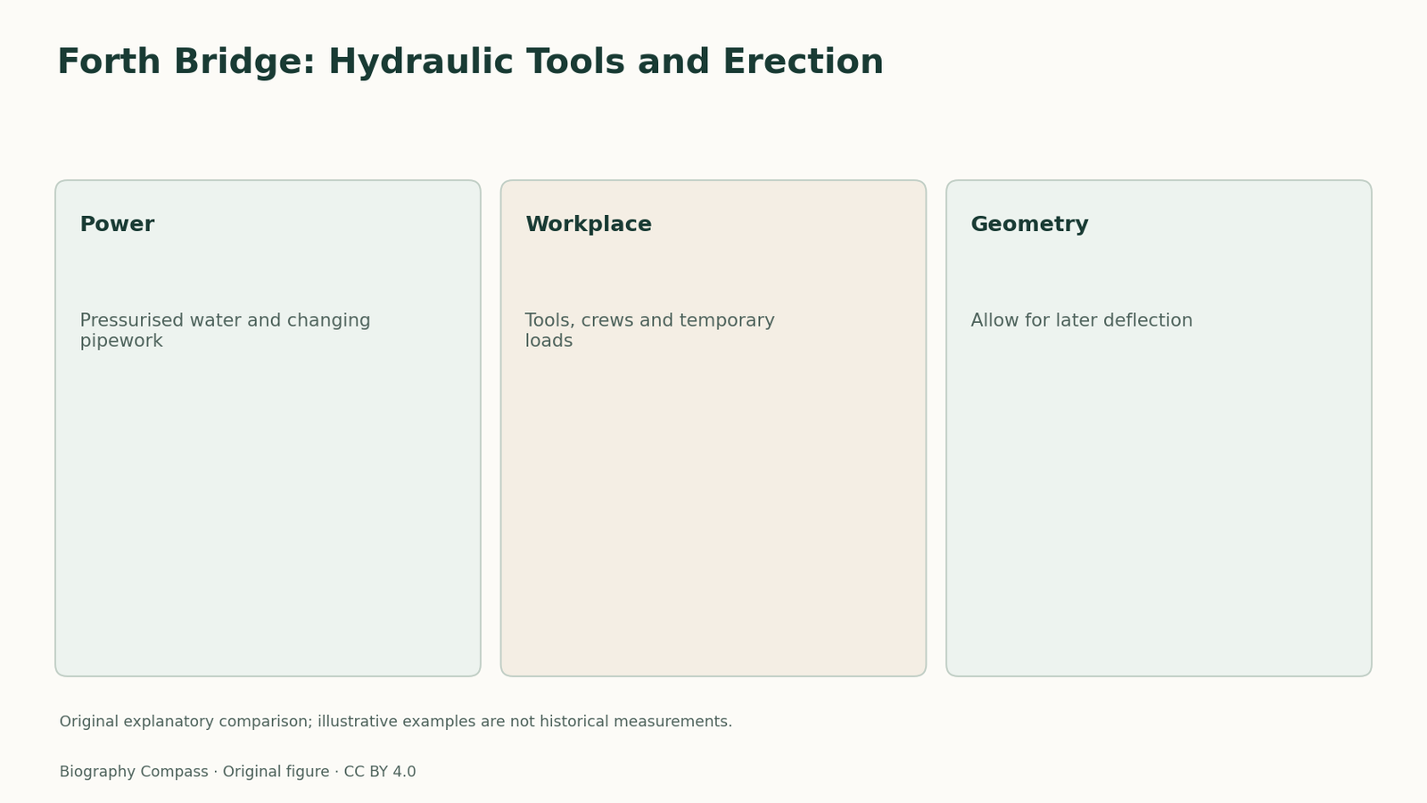
The Forth Bridge’s hydraulic riveting equipment required a supply system extending from its pressure-producing apparatus to machines on the rising structure. The ICE museum describes compressed water delivered up the towers and along the cantilevers, with pipework adjusted as construction progressed. This was an operating network within the construction site. It differed from the permanent bridge’s function of supporting trains. Studying that distinction makes Arrol’s contribution concrete: fabricating and erecting an immense steel structure required tools that could work where each new connection had to be made.
A worked comparison
What each part contributes
Use the specific distinctions developed in the study.
| Part or record | What it establishes | Why the distinction matters |
|---|---|---|
| Water-pressure lines | Delivery to working tools | Supply and point of use are separate |
| Riveting | Forms a structural connection | Requires access and suitable support |
| Setting out | Anticipates later movement | Different from final unloaded position |
How did power reach a riveter above the water?
The Forth Bridge’s hydraulic riveting equipment required a supply system extending from its pressure-producing apparatus to machines on the rising structure. The ICE museum describes compressed water delivered up the towers and along the cantilevers, with pipework adjusted as construction progressed. This was an operating network within the construction site. It differed from the permanent bridge’s function of supporting trains. Studying that distinction makes Arrol’s contribution concrete: fabricating and erecting an immense steel structure required tools that could work where each new connection had to be made.
Water, compressed air and oil were separate supplies
Westhofen’s contemporary page describes separate pipes for the water working hydraulic riveters, compressed air and oil for furnaces. It also describes oil descending from a tank by gravity. Those lines served different equipment and cannot be treated as interchangeable versions of hydraulic power. The distinction helps explain the site as an operating workplace: a riveting tool needed its pressure supply, while a furnace needed fuel. Extending steelwork therefore created utility and maintenance tasks as well as a new place to fasten another structural member.
Sources for this section: [3]
The unfinished bridge carried construction equipment too
Westhofen’s 1890 account describes cranes, temporary girders, winches, boilers, furnaces, ropes and staging supported on the cantilevers. Those loads existed before the eventual railway service. Erection planning therefore could not consider only the weight of the final structural members. Equipment made assembly possible while also adding weight and requiring working space. The source’s explanation shows a genuine construction interface: the partially completed structure supported the means by which its next sections were installed, and the temporary arrangement changed as the work advanced.
Sources for this section: [3]
Position during erection anticipated later deflection
The same contemporary account explains that cantilever sections were set higher than the desired final position to allow for deflection as further members were added. The final unloaded camber and the setting-out allowance were related but different quantities. This was not a decorative upward curve added after construction. It was a sequencing decision based on expected movement of the growing structure. Together with the hydraulic supply, it illustrates why the construction record adds something beyond the consulting designers’ names or the date on which the permanent railway opened.
Sources for this section: [3]
Construction-interface exercise and checked answer
A fictional contractor has a working hydraulic riveter and adequate pressure at ground level, but no completed pipe connection to the next work position. Is the machine ready to form that joint? No: supply must reach the point of use, and the machine and crew need suitable access and support. A second question asks whether setting a member at its intended final level necessarily accounts for the deflection caused by later construction. Again, no. The checked answer considers the changing load sequence. These examples identify practical dependencies without inventing a measured pressure, erection load or deflection for Arrol’s actual equipment.
Continue the chronology
Related history guides
Tay Bridge 1880: Wind and Bracing
Compare the Tay Bridge inquiry’s wind, bracing and connection evidence, keeping its two 1880 reports distinct and testing a simple force calculation.
Read the timeline1922–1924Sydney Bridge 1924: Comparing Tenders
Read the original 1924 Sydney Harbour Bridge tender report through firms, options, compliance, metalwork and fabrication plans, with a comparison exercise.
Read the timeline1881–1890Forth Bridge: Partnership, Approval and Building
Map Fowler, Baker and the contractors’ roles on the Forth Bridge using design reports, contract dates and construction records, with a worked exercise.
Read the timelineBiography context
Explore United Kingdom through connected lives
Connected biographies
People and wider context
1839–1913
William Arrol
engineering contractor and structural-steel manufacturerWilliam Arrol was a engineering contractor and structural-steel manufacturer, known for bridge construction, erection equipment and hydraulic riveting.Read biographyQuick answers
Common questions
- Was all equipment carried by the Forth cantilevers part of the finished railway?
- No. The contemporary account describes temporary cranes, furnaces, staging and other equipment needed during construction.
Primary and institutional sources
How this history was checked
Read the cited original records, institutional accounts and later interpretations. The comparison and exercise explain the specific evidence used in this study. This article was reviewed on 8 November 2026.