
The short answer
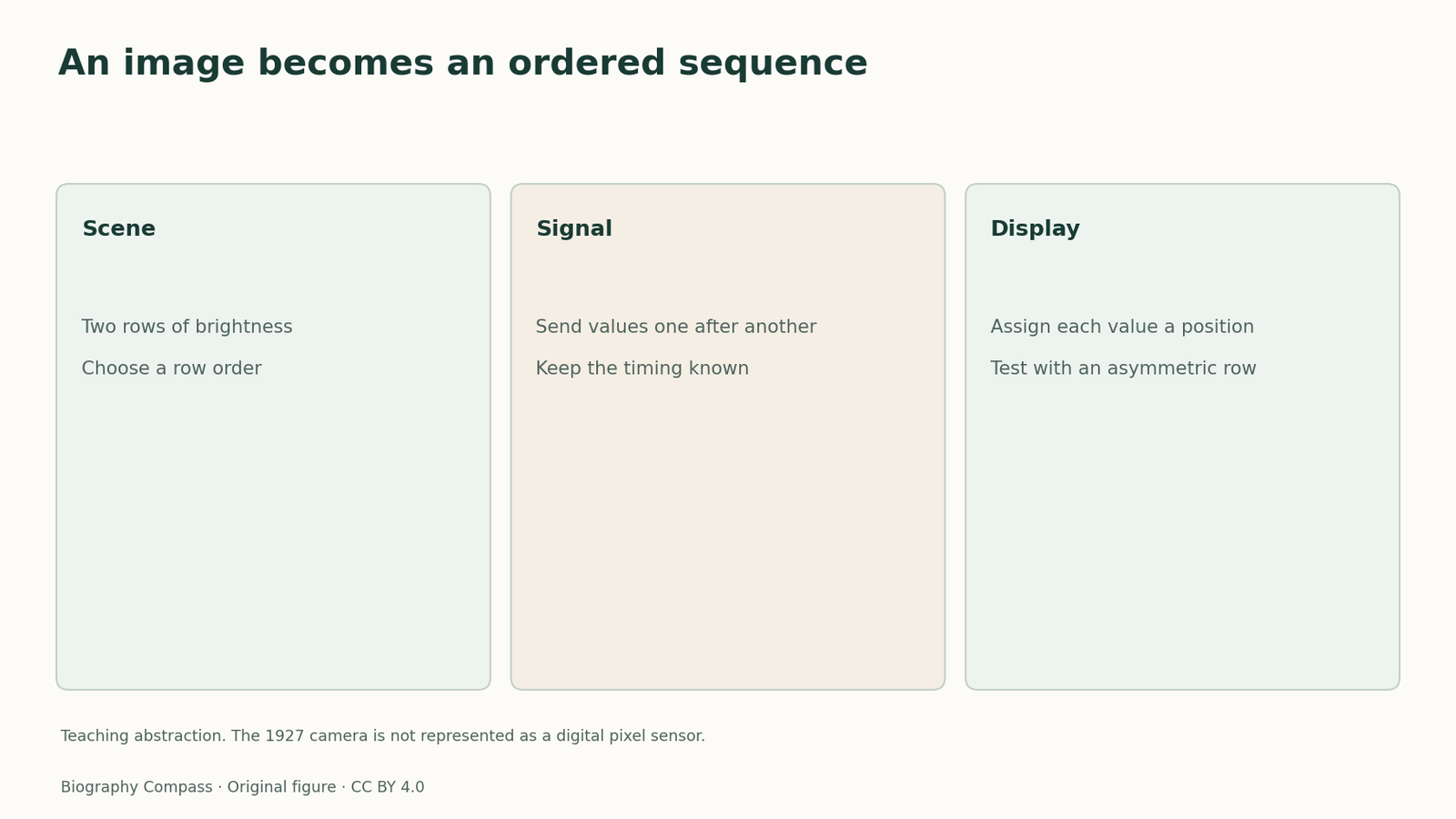
A single electrical channel cannot send a two-dimensional picture all at once. It can send a sequence whose order lets a receiver place the brightness values back where they belong.
Reading the evidence
Track the picture across three representations
The grid exercise isolates ordering from the camera’s physical design.
| Stage | Representation | What must be preserved |
|---|---|---|
| Scene | Positions with different brightness. | The pattern across the field. |
| Signal | Values in a known order. | Timing and sequence. |
| Display | Brightness restored to positions. | A scan matched to the sender. |
Find where the picture changes form
The 1927 tube in the Smithsonian collection takes a projected image at its front. The sensitive surface emits electrons, and only a small part of the resulting pattern contributes to the output at a given moment. Repeated scanning converts the scene into a signal that changes over time.
The system patent addresses how image information at the sending end can be used at a receiver. Follow three representations in the records: brightness across a surface, electrical output in time, and brightness positioned on the receiver’s display. Each change needs its own link in the explanation.
Rebuild a small invented picture
Draw two rows of three squares. Set the brightness values in the first row to 1, 0, 1 and in the second row to 0, 1, 0. Send the values left to right across each row, taking the upper row first. Another person can reconstruct the picture from the sequence if they know the dimensions and scanning order.
Reverse the order in the second row only, and ask whether this particular picture shows the error. It does not: that row reads the same in reverse. Replace it with 1, 1, 0 and repeat. Now the error becomes visible. A good test pattern exposes a proposed fault rather than merely looking plausible on the screen.
Separate the exercise from the instrument
The grid uses discrete values for teaching. It does not imply a digital pixel sensor in the museum object or assert a historical scanning rate. Its purpose is to show why shared timing and position matter even when a camera can produce an electrical response to light. To compare another camera, ask whether it samples emitted electrons directly or reads a pattern accumulated on a target.
Continue the chronology
Related history guides
Biography context
Explore United States through connected lives
Connected biographies
People in the records
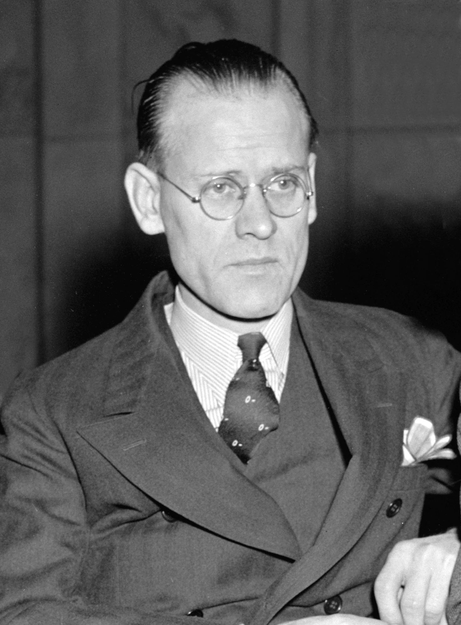
1906–1971
Philo Farnsworth
Electronic television inventorFarnsworth turned a projected picture into a stream of signals using an electronic camera tube.Read biographyQuick answers
Common questions
- Why use an asymmetric test pattern?
- An asymmetric pattern can reveal a reversal or misplaced section that would be invisible in a symmetric test image.
Primary and institutional sources
How this history was checked
Dates, legal milestones and historical claims are checked against the official and institutional records below. This article was reviewed on 5 November 2026.